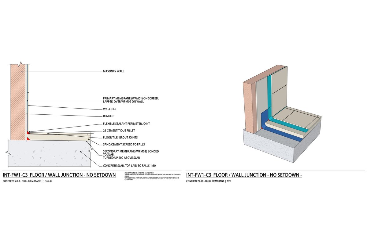
What a generic waterproofing detail is for
Most waterproofing failures are not membrane failures. They are junction failures: the floor/wall corner where the membrane was not turned up, the door threshold with no waterstop, the shower screen sitting on tiles with nothing under it, the floor waste where the membrane stops short of the flange. A generic detail shows what that junction looks like when it is done properly, before the project drawings exist, so the builder, the certifier and the waterproofer are looking at the same picture. These sheets are the Excelo library: one geometry per junction, drawn as a 2D section and a peeled 3D view, built for every substrate system we specify.
The five internal systems
Concrete slab with a single membrane below an unbonded screed (C1): the membrane is bonded to the slab, the screed floats on it, and the screed holds water that must drain to the waste flange through weep holes. Concrete slab with a single membrane above a bonded screed (C2): the screed is bonded, the membrane sits under the tiles, and the waste is a leak control flange at membrane level. Concrete slab with a dual membrane (C3): a secondary membrane on the slab, a bonded screed, a primary over it. Compressed fibre-cement sheet floor on framing, single membrane (F1): membrane on the sheet, mortar bed over. And the ECE standard for sheet floors, F2: a secondary membrane on the sheet, a bonded screed, and the primary membrane over the screed. Every internal junction is drawn in each system that makes sense for it, and the generator tells you when it has to fall back to the nearest one.
External and below ground
Balcony and roof details come in a liquid-membrane version tiled on a screed (E1) and a two-layer torch-on sheet version with protection (E2): the balcony edge with drip trim and weepholes, door sills with and without a sub-sill, upturns with a reglet or a termination bar, terminations behind cladding, outlets, overflows, movement and construction joints, planters, pedestal paving, balustrade posts and penetrations. Basement details show the sheet membrane with hydrophilic waterstops at the footing, the wall/floor kicker, pile heads, pipe penetrations, retaining walls with drainage, a core-filled H-block wall, and a shotcrete and soldier-pile junction.
How to read the sheets
The 2D section is drawn at 1:5 where it fits an A4 landscape sheet. The membrane is one cyan line at a constant drawn thickness whether it is liquid or sheet; the label says which. Fillets are red and sealant is yellow, so you can see at a glance where the bond breakers go. Tiles sit straight on the membrane or screed: tile adhesive is never drawn, because it is not a waterproofing layer. The substrate under a membrane falls toward the waste, and so does the membrane. The 3D page peels the build-up back one layer at a time in the order it is built. The notes on each sheet name the clauses the detail relies on.
Why the stamp
A detail drawn for no particular building cannot know your membrane system, your slab set-downs, your screen extrusions or your waste positions. That is what a project waterproofing design is for, and it is also what the NSW Design and Building Practitioners Act expects a registered design practitioner to declare. So every sheet carries the words generated for indicative purposes only, not for construction, and the PDF repeats them on each page. Use them to brief, to tender, to check a tenderer's proposal and to explain a junction on site. Then get the project details done.